
 Product
 Brand
Brand Articles
 Tools
Tools
What is a Monostable Multivibrator?
Monostable Multivibrator using BJT Explained
Catalog
| I. Circuit and Waveform | |
| II. MOSFET | |
| III. Building a basic monostable multivibrator circuit | 1. NOR Gate |
| 2. 74LS121 Monostable Multivibrator | |
I. Circuit
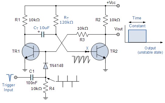
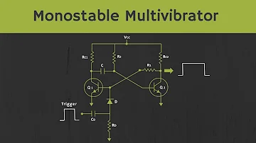
The circuit of monostable multivibrator
The monostable multivibrator circuit is shown above. When power is first applied, the base of transistor TR2 is connected to Vcc through a bias resistor, and R T makes the transistor "fully on" and into a saturated state, and at the same time, TR1 is "closed" in the process. Then, this represents the "steady state" of the circuit with zero output. Therefore, the current flowing into the saturation base of TR2 will be equal to Ib = (Vcc-0.7)/RT.
If a negative trigger pulse is now applied to the input, the fast decay edge of the pulse will pass directly through the capacitor, C1 to the base of the transistor, and TR1 will “turn on” it through the blocking diode. The collector of TR1 of the previous Vcc quickly dropped below zero volts, effectively making the capacitor C T reverse the charge on its board to -0.7v. This action causes the transistor TR2 to now have a negative base voltage at X, thereby completely "turning off" the transistor. Then, this represents the second state of the circuit, the "unstable state", and the output voltage is equal to Vcc.
The timing capacitor, C T begins to discharge, trying to charge to the power supply voltage Vcc. The negative voltage at the bottom of transistor TR2 starts to combine with R T C T. When the base voltage of TR2 increases back to Vcc, the transistor starts to turn on, so that the transistor TR1 is "turned off" again. As a result, the monostable multivibrator automatically returns to its original stable state, waiting for the second negative trigger pulse to restart the process.
The monostable multivibrator can generate very short pulses or long rectangular waveforms, the leading edge of which rises with time with the externally applied trigger pulse, and the trailing edge depends on the RC time constant of the feedback element used. This RC time constant can be changed over time to produce a series of pulses with a controlled fixed time delay relative to the original trigger pulse.
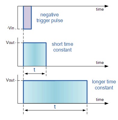
The waveform of monostable multivibrator
The time constant of Monostable Multivibrators can be changed by changing the value of the capacitor, C T resistor, R T, or both. The monostable multivibrator is usually used to increase the pulse width or generate a time delay in the circuit because the frequency of the output signal is always the same as the frequency of the trigger pulse input, the only difference is the pulse width.
II. MOSFET
Monostable multivibrators have only ONE stable state (hence their name: "Mono") and generate a single output pulse when triggered externally. The monostable multivibrator returns to its initial and stable state only after a certain period of time determined by the time constant of the RC coupling circuit.
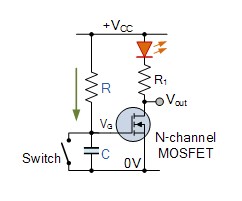
Consider the MOSFET circuit on the left. Resistor R and capacitor C form an RC timing circuit. The N-channel enhancement mode MOSFET is turned on due to the voltage across the capacitor, and the drain connected to the LED is also turned on.
When the switch is closed, the capacitor is short-circuited, so the gate of the MOSFET is short-circuited to the ground while discharging. Both MOSFET and LED are switched to "OFF". When the switch is closed, the circuit will always be in the "OFF" state and in an "unstable state".
When the switch is opened, the fully discharged capacitor begins to charge through the resistor, R at a rate determined by the RC time constant of the resistor-capacitor network. Once the capacitor charging voltage reaches the lower threshold voltage level of the MOSFET gate, the MOSFET will "turn on" and light up the LED, restoring the circuit to a stable state.
Then the application of the switch causes the circuit to enter its unstable state, and the time constant of the RC network restores it to a stable state after a preset timing period, resulting in a very simple "one-shot" or monostable multivibrator MOSFET Circuit.
Monostable multivibrator or "single multivibrator", also known as "monostable multivibrator", is used to generate a single output pulse of a specified width, or when a suitable external trigger signal or pulse is applied For T, "HIGH" or "LOW". The trigger signal starts a timing period, which causes the monostable output to change its state at the beginning of the timing period and maintain the second state.
The timing period of the monostable state consists of the time constant of the timing capacitor, C T, and resistance R T until it resets or returns to its original (stable) state. Then the monostable multivibrator will remain in this original stable state indefinitely until it receives another input pulse or trigger signal. Then, the monostable multivibrator has only ONE stable state, and goes through a complete cycle in response to a single trigger input pulse.
III. Building a basic monostable multivibrator circuit
1. NOR Gate

A monostable NOR gate
First, assume that the trigger input is low at logic level "0", so that the output of the first NOR gate U1 is high at logic level "1" (NOR gate control principle). The resistor R T is connected to the supply voltage and therefore is also equal to the logic level "1", which means that the capacitor C T has the same charge on both boards. Therefore, junction V1 is equal to this voltage, so the output of the second NOR gate U2 will be low at logic level "0". Then, this means the circuit is "steady state" and the output is zero.
When a positive trigger pulse is applied to the input at t 0, the output of the first NOR gate U1 goes low, and the left side plate C T of the capacitor discharges the capacitor. Since the two plates of the capacitor are now at logic level "0", so is the input of the second NOR gate, and U2 causes the output to be equal to logic level "1". Then, this represents the second state of the circuit, the "unstable state", with the output voltage equal to +Vcc.
The second NOR gate, U2 will remain in the second unstable state, until the timing capacitor is charged through the resistor, and RT reaches the minimum input threshold voltage of U2 (about 2.0 V) to make it change state because of the logic level "1" value Now appears on its input. This will reset the output to logic "0" and then feedback (feedback loop) to an input of U2. This operation will automatically return the monostable state to its original stable state and wait for the second trigger pulse to restart the timing process again.
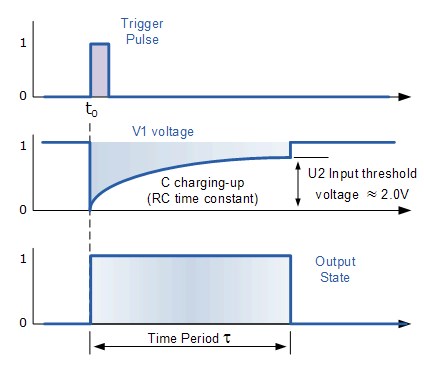
The waveform of a monostable NOR gate
Give an equation for the circuit time period:
In this equation, R is in Farad's Ω and C.
2. 74LS121 Monostable Multivibrator

We can also use a dedicated IC to make a monostable pulse generator, and there are already dedicated integrated circuits, such as 74LS121 standard one-shot monostable multivibrator or 74LS123 or 4538B retrigger monostable multivibrator. The output pulse width is generated by using only two external RC timing components, from as low as 40 nanoseconds to 28 seconds, the pulse width is given as: T = 0.69RC, in seconds.
This monostable pulse generator IC can be configured to generate a rising edge trigger pulse or a falling edge trigger pulse of the output pulse. 74LS121 can generate about 10ns to about 10ms wide pulse width, the maximum timing resistance is 40kΩ, the maximum timing capacitance is 1000uF.
To summarize, the steady-state multivibrator circuit has only ONE steady state, making it a "one-shot" pulse generator. When triggered by a short external trigger pulse, whether it is positive or negative.
Once triggered, the monostable state changes to state and stays in the second state for a period of time determined by the preset time period of RC </span> using the feedback timing component. After a time period has passed, the monostable state automatically returns to the original low state, waiting for the second trigger pulse.
The monostable multivibrator can therefore be regarded as a trigger pulse generator, usually used to generate a time delay as an output signal. The frequency of the output signal is the same as the frequency of the trigger pulse input. The only difference is the pulse width.
A major disadvantage of "monostable multivibrators" is the time between applications. The next trigger pulse must be greater than the circuit's preset RC time constant to allow the capacitor to charge and discharge time.
 UTMEL
UTMEL
We are the professional distributor of electronic components, providing a large variety of products to save you a lot of time, effort, and cost with our efficient self-customized service. careful order preparation fast delivery service
What is a monostable multivibrator used for?
Monostable multivibrators are generally used to increase the width of a pulse or to produce a time delay within a circuit as the frequency of the output signal is always the same as that for the trigger pulse input, the only difference is the pulse width.
What is the difference between astable and monostable multivibrator?
Astable multivibrator, in which the circuit is not stable in either state —it continually switches from one state to the other. Monostable multivibrator, in which one of the states is stable, but the other state is unstable (transient). A trigger pulse causes the circuit to enter the unstable state.
Which mode can be used as a monostable multivibrator?
Frequency Divider When the IC 555 is used as a monostable multivibrator, a positive going rectangular pulse is available at the output when a negative going pulse of short duration is applied at the trigger input.
 Discovering New and Advanced Methodology for Determining the Dynamic Characterization of Wide Bandgap DevicesSaumitra Jagdale15 March 20242669
For a long era, silicon has stood out as the primary material for fabricating electronic devices due to its affordability, moderate efficiency, and performance capabilities. Despite its widespread use, silicon faces several limitations that render it unsuitable for applications involving high power and elevated temperatures. As technological advancements continue and the industry demands enhanced efficiency from devices, these limitations become increasingly vivid. In the quest for electronic devices that are more potent, efficient, and compact, wide bandgap materials are emerging as a dominant player. Their superiority over silicon in crucial aspects such as efficiency, higher junction temperatures, power density, thinner drift regions, and faster switching speeds positions them as the preferred materials for the future of power electronics.
Read More A Comprehensive Guide to FPGA Development BoardsUTMEL11 September 202520363
This comprehensive guide will take you on a journey through the fascinating world of FPGA development boards. We’ll explore what they are, how they differ from microcontrollers, and most importantly, how to choose the perfect board for your needs. Whether you’re a seasoned engineer or a curious hobbyist, prepare to unlock new possibilities in hardware design and accelerate your projects. We’ll cover everything from budget-friendly options to specialized boards for image processing, delve into popular learning paths, and even provide insights into essential software like Vivado. By the end of this article, you’ll have a clear roadmap to navigate the FPGA landscape and make informed decisions for your next groundbreaking endeavor.
Read More 800G Optical Transceivers: The Guide for AI Data CentersUTMEL24 December 202510610
The complete guide to 800G Optical Transceiver standards (QSFP-DD vs. OSFP). Overcome supply shortages and scale your AI data center with Utmel Electronic.
Read More The 2026 Engineer’s Guide: Choosing the Right MCU for Your Next IoT & New Energy ProjectUTMEL30 April 2026839
A comprehensive comparison of 2026's leading MCUs from ST, NXP, and Microchip across power efficiency, processing performance, connectivity, and ecosystems to help engineers select the optimal chip for next-gen IoT and new energy projects.
Read More AI Server Components: Engineering Next-Gen Data Center Hardware for 100kW RacksUTMEL15 May 2026423
The transition from traditional enterprise IT to AI-driven workloads has rendered legacy data center hardware obsolete, forcing infrastructure planners to re-engineer server components for extreme thermal environments.
Read More
Subscribe to Utmel !
![HCS360/P]() HCS360/P
HCS360/PMicrochip Technology
![AD8232ACPZ-RL]() AD8232ACPZ-RL
AD8232ACPZ-RLAnalog Devices Inc.
![AD9173BBPZ]() AD9173BBPZ
AD9173BBPZAnalog Devices Inc.
![ATA663254-GBQW]() ATA663254-GBQW
ATA663254-GBQWMicrochip Technology
![ATECC108A-RBHCZ-T]() ATECC108A-RBHCZ-T
ATECC108A-RBHCZ-TMicrochip Technology
![HCS362T-I/ST]() HCS362T-I/ST
HCS362T-I/STMicrochip Technology
![AT88SC12816C-PU]() AT88SC12816C-PU
AT88SC12816C-PUMicrochip Technology
![FM3164-GTR]() FM3164-GTR
FM3164-GTRCypress Semiconductor Corp
![FOD4116]() FOD4116
FOD4116ON Semiconductor
![HCS301/P]() HCS301/P
HCS301/PMicrochip Technology


